


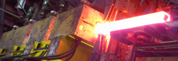
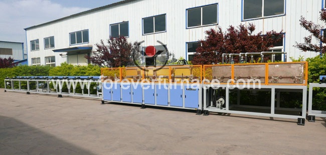
The structure of medium frequency Hardening heat treatment furnace for remote extension mechatronics. The quenching of medium frequency heat treatment and tempering equipment is composed of bed, V-shaped bracket, movable rod, sliding table with belt, quenching transformer inductor group, capacitor and quenching slot, etc. The mechanical action is controlled by hydraulic pressure, and the V-shaped bracket holds the workpiece up and down in place, and then coordinates the action by the moving rod. The two camshafts on the sliding table move horizontally to enter or send the camshaft into or out of the sensor. The left spindle box of the machine tool is driven by hydraulic motor to rotate the camshaft. The speed can be adjusted stepless in a certain range. There is a copper plate grounding ring on the left side of the inductor. If the camshaft is not clamped on it, it will first touch the ground ring when it moves horizontally, generate a signal and stop moving.
Quenching transformer is a variable turn ratio intermediate frequency transformer, the primary is 10 times 22 turns, divided into 13 grades, secondary 6 turns. The sensors are in series in multiple circles, and nine sensors are located on a center line, eight of which are heated cams. The sensor is double-turn, the gap between the cam tip and the inner diameter of the effective ring is 4 × 5 mm, and the sensor base has an elliptical hole, so that the sensor can be adjusted relative to the axial position of the cam. The camshaft sensor adopts series, which avoids the disadvantages of short intermediate conductive path and long conductive path at two ends when multiple sensors are connected in parallel. When the medium frequency quenching and quenching heat treatment equipment adopts the series inductor method, if the temperature of the intermediate cam is on the high side, it can also be adjusted by increasing the gap. Capacitor bank configuration, using three bottles of 300kvar electric thermoelectric containe
Red polonium thermometer. The infrared thermometer monitors the camshaft heating temperature, which is installed 0.5 m from the center of the inductor. The lens on the sensor is aimed at the side of a cam, such as the final heating temperature of a camshaft is too low. The heat treatment equipment will send out the unqualified signal of the infrared thermometer, and the rejection manipulator in front of the quenching tank will be lifted so that the camshaft does not enter the quenching tank. Air pumping device. The upper part of the sensor and the upper part of the quenching tank conveyor chain lifting workpiece are equipped with a suction cover to keep the fresh environment near the station.

Overseas manager: Tom Wang
Email:tom@foreverfurnace.com
Phone: 0086-13303078975(whatsapp, wechat,line)
Specialist of bar heat treatment furnace in China; Glad to be your business partner in induction heating field.
Post time: 06-05-2019